Overview
This page covers any general information for the Fly-Gemini-V3 board.
It is currently available through AliExpress.
The upgraded Gemini V3 motherboard now has 1GB of DDR Ram on board, allowing a full desktop (based on Armbian) to be ran. All drivers support up to 48V voltage. The board can be used with both Klipper and RRF firmware and can even can run klipper screen while using the latest SHT board. The Gemini v3 has both a control board (STM32) and linux board in one package, a Raspberry Pi is not required.
Enhanced 5v power supply protection reduces the probability of chip damage. The SD card for the MCU chip has been removed, and a HID bootloader had been implemented to install the firmware. An onboard Can transciever has replaced the V2 Can Hat. USB to CAN bridge is now supported.
The M2WE EMMc+SDIO extension supports 2.4G/5G dual-band WiFi and 16G storage function to the motherboard.
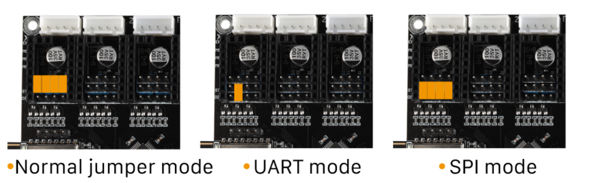
Driver Jumpers
The jumpers should be installed as below. “Common Interpolation” should be used for standalone drivers. “SPI mode Interpolation” is supported for TMC5160 drivers. “UART mode Interpolation” should be used when using smart drivers (i.e. TMC2208, TMC2209, TMC2225 and TMC2226)
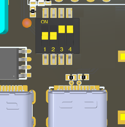
USB-CAN bus DIP Switches
The Fly Gemini V3 has DIP switches that configure the internal link between the SBC and MCU sides of the board. When the switches are enabled for internal USB or CAN bus the lower right USB-A port will be disabled. The USB-A port wil be enabled when the switches are all in the off position OR if switches 3 and 4 are on to connect the MCU to it’s USB C port.
Set Switches 1 and 2 to the ON position to connect the SBC to the STM32F405 MCU over the internal USB connection.
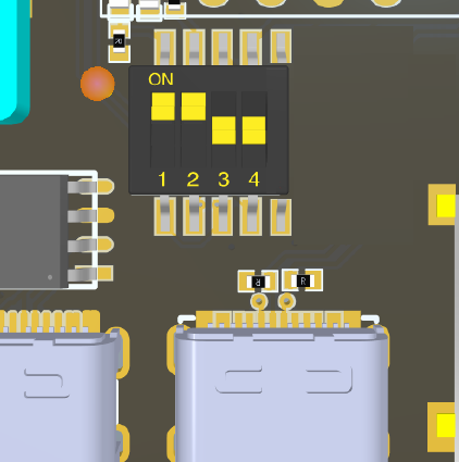
Set Switches 3 and 4 to the ON position to connect the STM32F405 to the external USB C port.
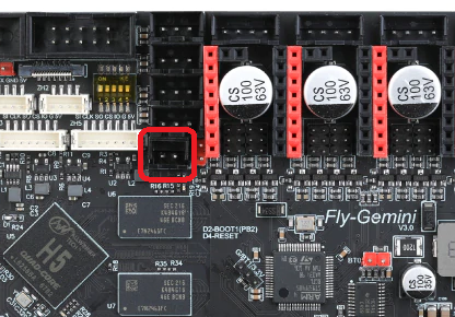
Driver Diag Pin
The driver diag pin is used for sensorless homing and stall detection.
The Fly-Gemini-V3 does not have a way of disabling the diag pin as it is designed to be used with Fly-2209 drivers which have a switch on the underside of them for disabling the diag pin. Set the dip switch to ‘ON’ to enable the diag pin.
If you plan on using endstops rather than sensorless homing and do not have the Fly-2209 drivers, you need to bend or remove the diag pin.
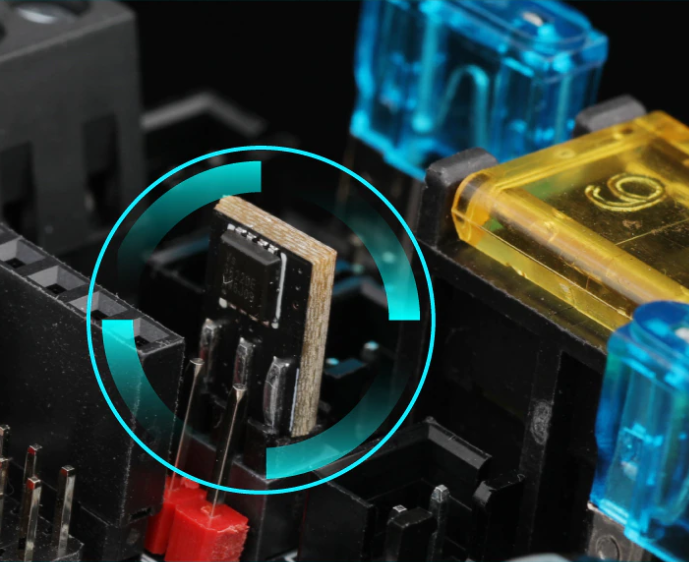
Fan Mosfets
The Fly-Gemini-V3 features a replacable fan mosfet module (VS3622e) that controls the two fan outputs.
If the MOSFET is damaged by an accidental short circuit it can easily be replaced. New Fly-MOS modules can be purchased from the Mellow store
The Fan MOS design allows it to be inserted in either orientation.
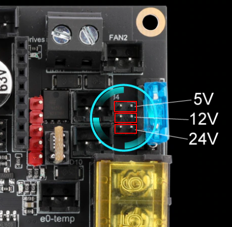
Fan Voltage
The fan voltage can be set using jumpers to either 5v, 12v and Vin.
Set them as shown below.
5V Core Fan
The Fly-Gemini-V3 features a 5v fan header for cooling the CPU. Fan control can be configured in Klipper.
Maximum Input voltage
Board/Bed Power
The board power input can handle voltage up to 30v.
Driver Power
The driver power input can handle voltage up to 62v.
Initial Installation
The board that you will receive doesn’t have any firmware installed so when plugged into a computer, the board will show as an unidentified device. Follow the SBC instructions to build an SD card with Fly OS. If you have purchased the optional M2WE 16G eMMC & 5G Wifi board it will come with the FLY OS pre installed on the M2WE.