General information regarding the Fly-CDYv2
Edit me
Overview
This page covers any general information for the Fly-CDYv2 board.
It has been replaces by the Fly-CDYv3
Features
- 32-bit ARM Cortex-M4 series 168 MHz, STM32F407ZGT6 chip
- Supported Firmware: Marlin 2.0, Reprap, and Klipper
- Drivers supported: A4988, LV8729, DRV8225, TMC2208, TMC2209, & TMC5160
- Drive mode support: TMC: UART, & SPI
- Support for 6 independent motor drives, 3 extruders, and 3 PWM fans
- All drivers support up to 24 volts.
- Supported Displays: serial touch screen, 12864 LCD, 2004 LCD , FLY 4.3, & 7.0 V1
- Supports automatic bed leveling sensor: BLTouch
- WIFI chip:esp32 ( 1 . 6M / s ) Supported with Reprap firmware
- PWM Fan MOS boards can be directly replaced in case of damage.
- Drive signal output voltage:3.3V 5v ( default ) 12V
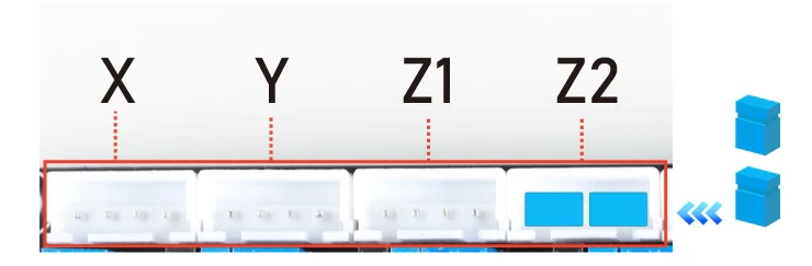
Z Driver Jumpers
If only one Z output is being used, jumpers should be installed on the other Z output as shown below.
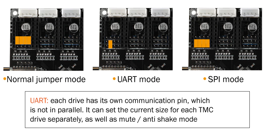
Driver Jumpers
Driver communication jumpers
Power Configuration
The Fly-CDYv2 has one 24v input and one ground.
Maximum Input voltage
The board can handle an input voltage up to 32v.
Thermistor inputs
Natively, the Fly-CDYv2 supports PT1000 and standard thermistors (with a 4k7 pullup resistor) and has a total of 4 temperature sensor inputs.
It is possible to connect a PT100 or K type thermocouple using an external module.
Initial Installation
The board that you will receive doesn’t have any firmware installed so when plugged into a computer, the board will show as an unidentified device.
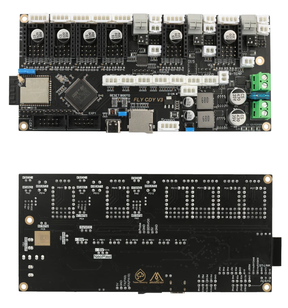
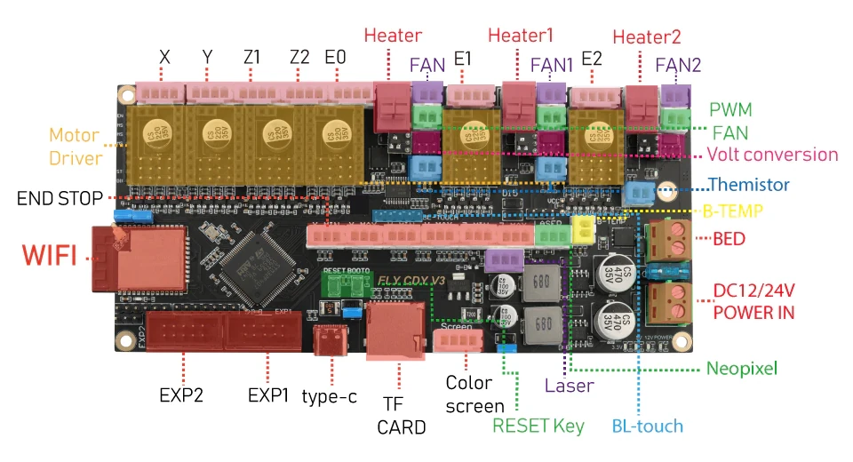
IO Pins
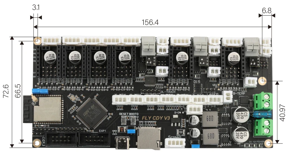
Dimensions