Fly UTOC-1 and UTOC-3 pin diagram
Edit me
Fly UTOC-1 and UTOC-3 pin diagram
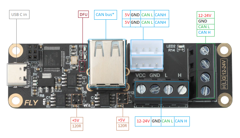
Table of pin functions
| Device | Function |
|---|---|
| USB C | USB in from host |
| DFU | Device Firmware Update. Add jumper and restart the board to enter DFU mode for flashing firmware. |
| +5V | 5v from USB or from onboard 24v to 5v regulator. |
| 12-24V | VCC in 12 to 24 volts |
| GND | Ground |
| 120r | 120 ohm resistor for CAN bus termination |
| CAN L | CAN bus high line |
| CAN H | CAN bus low line |
| CAN bus | USB A ports for connecting to STM32 boards without an onboard CAN port. Supports CAN bus with some STM32 CPUs connected to the PA11/PA12 USB port with klipper firmware. |