Fly-SB2040-V1 pin map
Edit me
Fly-SB2040-V1 pin map
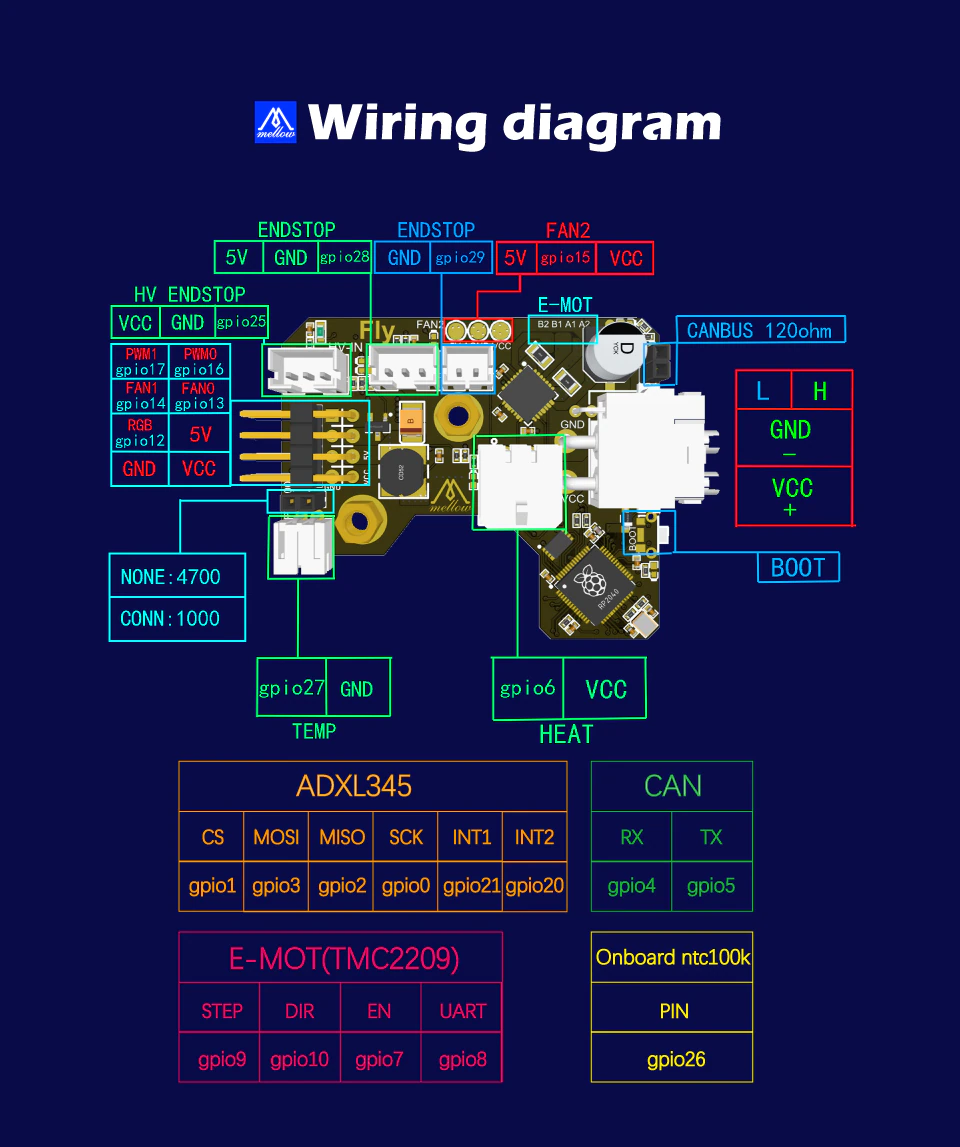
Table of pin functions
| Device | Function | Pin number | Alias |
|---|---|---|---|
| CAN BUS | CAN-RX | gpio4 | |
| CAN BUS | CAN-TX | gpio5 | |
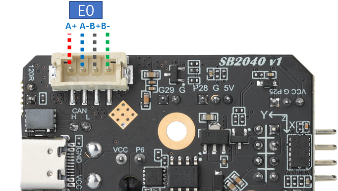
| Extruder | EN | gpio7 | EXT_EN |
| Extruder | STEP | gpio9 | EXT_STEP |
| Extruder | DIR | gpio10 | EXT_DIR |
| Extruder | UART | gpio8 | EXT_UART |
| Endstop | 0 | gpio28 | LIMIT_0 |
| Endstop | 1 | gpio29 | LIMIT_1 |
| Endstop | HV 2 | gpio25 | LIMIT_2 |
| Hotend | Heater | gpio6 | HE0 |
| Hotend | Tempreture | gpio27 | TH0 |
| Chamber | Tempreture | gpio26 | TH1 |
| Fans | Fan 0 | gpio13 | FAN0 |
| Fans | Fan 1 | gpio14 | FAN1 |
| Fans | Fan 2 | gpio15 | FAN2 |
| SPI | CLK | gpio0 | |
| SPI | MISO | gpio2 | |
| SPI | MOSI | gpio3 | |
| SPI | ADXL-CS | gpio1 | ADXL |
| SPI | ADXL-INT1 | gpio21 | |
| SPI | ADXL-INT2 | gpio20 | |
| LED | RGB LED | gpio12 | RGBLED |
| LED | Status LED | gpio25 |
Sample Configuration file: Fly-SB2040-V1.cfg
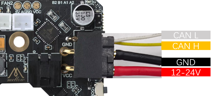
XT30 2+2 Wiring
| *Color | Function |
|---|---|
| RED | 12/24V |
| BLACK | GND |
| YELLOW | CAN H |
| WHITE | CAN L |
Extruder Wiring
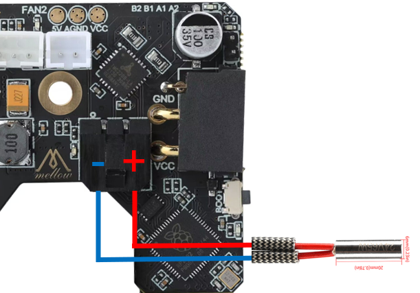
Hotend Wiring
- The heating circuit supports a maximum current of 10A
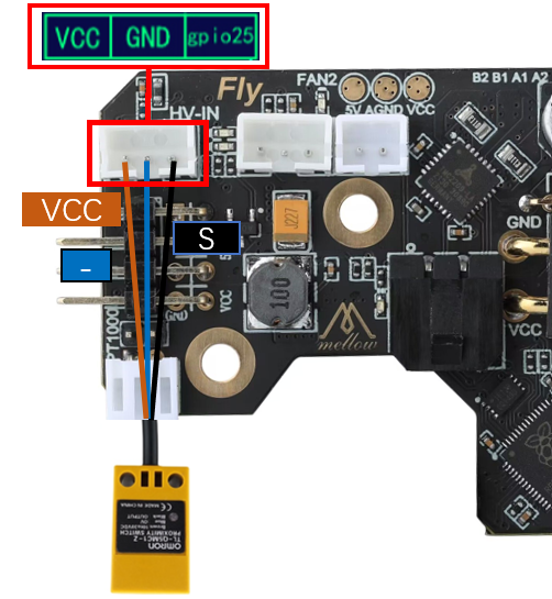
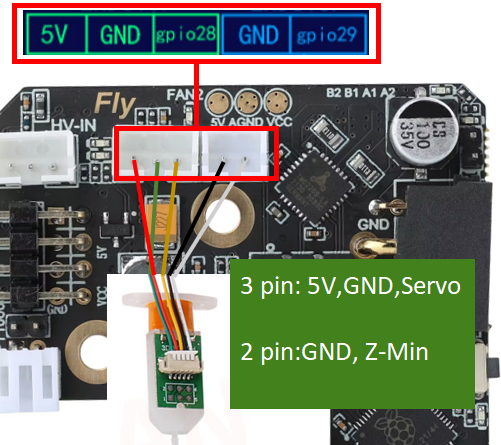
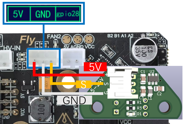
Z Probe Wiring
Induction Probe
- The official recommendation of VORON is to use the Omron Omron TL-Q5MC
Klicky Probe
- Klicky is a third-party leveling sensor that can be made at home at a very low cost, and its performance is stable and cost-effective. The wiring method is shown in the figure below.
BL Touch
- BL-touch has a total of five wires, three for the first group, responsible for the power supply of the sensor and the retraction of the probe, and the second group for the ground and signal lines, which output the limit signal. Please carefully check the wiring sequence when wiring the BL-touch, the wrong wiring may permanently damage the sensor and motherboard!!! The wiring method is shown in the figure below.
Voron Tap
- Voron Tap is the latest leveling sensor solution released by the Voron team, which has the characteristics of high precision, strong stability and good adaptability. When wiring, please pay attention to the positive and negative poles can not be reversed, otherwise it will damage the Tap sensor and even the SHT tool board.
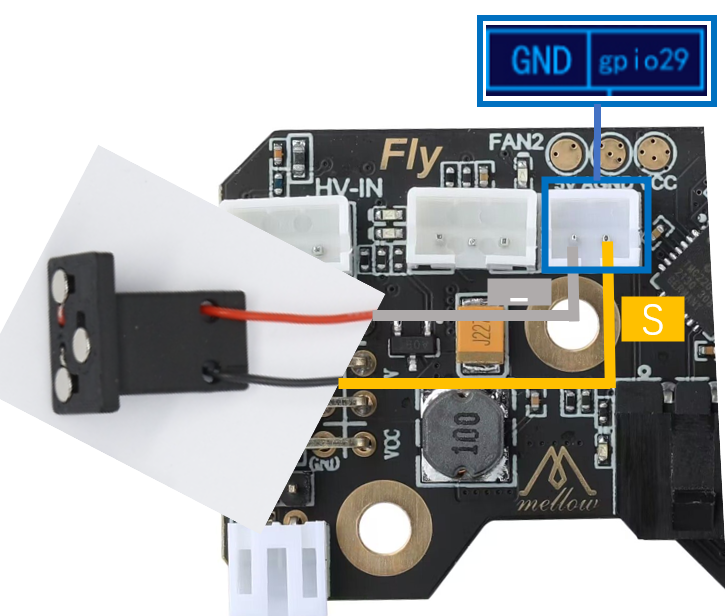
Limit switches
-
There are two types of limit switches: normally open (NO) and normally closed (NC). Generally, on 3D printers, it is recommended to use normally closed (NC), so that when there is a problem with the limit switch line, the system will report an error in time, which can avoid some unnecessary crashes and avoid damage to the printer.
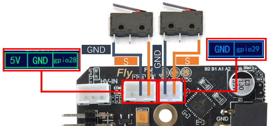
Fly-SB2040-V1 Limit Switches

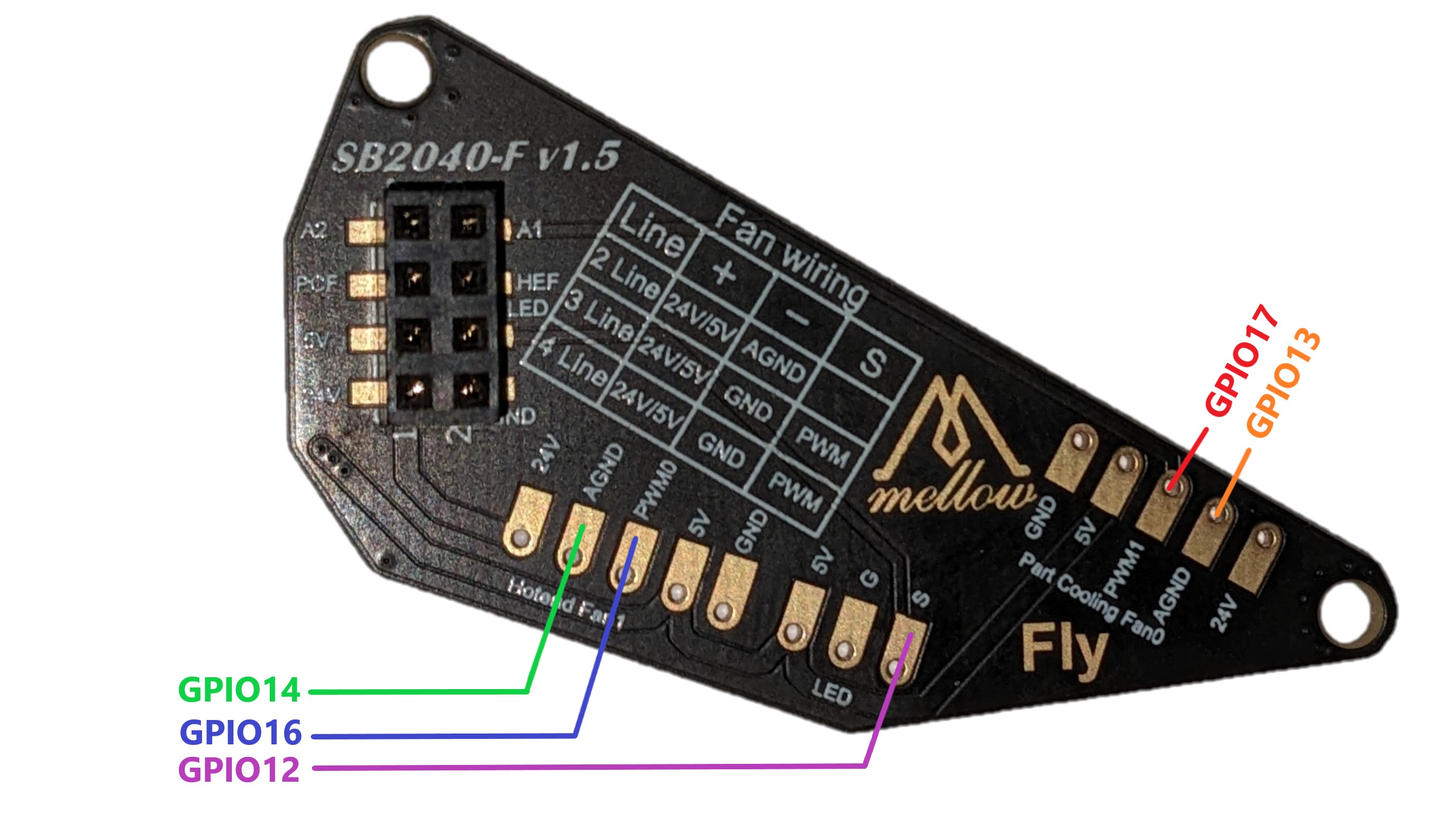
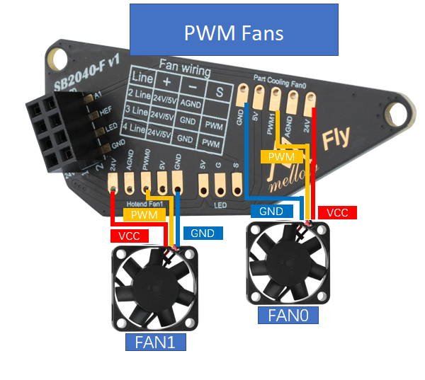
Fan Board Pins
| Device | Function | Pin number | Label at header | Label at Pad | Alias |
|---|---|---|---|---|---|
| Fans | Fan 0 | gpio13 | PCF | AGND(Part Fan) | FAN0 |
| Fans | Fan 1 | gpio14 | HEF | AGND(Hot End Fan) | FAN1 |
| Fan PWM | Fan 0 PWM | gpio17 | A1 | PWM1 | |
| Fan PWM | Fan 1 PWM | gpio16 | A2 | PWM0 | |
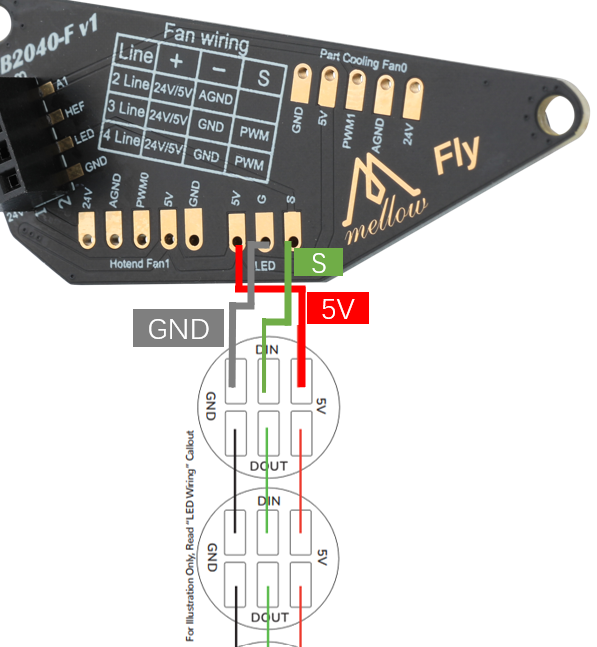
| LED | RGB LED | gpio12 | LED | S | RGBLED |
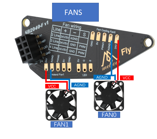
- SB2040 supports up to two controllable fans, fan voltage can be selected 24V, 5V, support 2, 3, 4-wire fans, wiring method is as follows.
RGB Wiring
- The positive and negative poles of the RGB LEDs must not be reversed, otherwise it will damage the CAN tool board.