Fly-ERCF-Easy-BRD-V1.1 pin map
Edit me
Fly-ERCF-Easy-BRD-V1.1 pin map
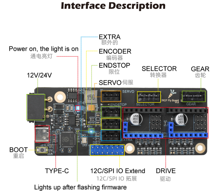
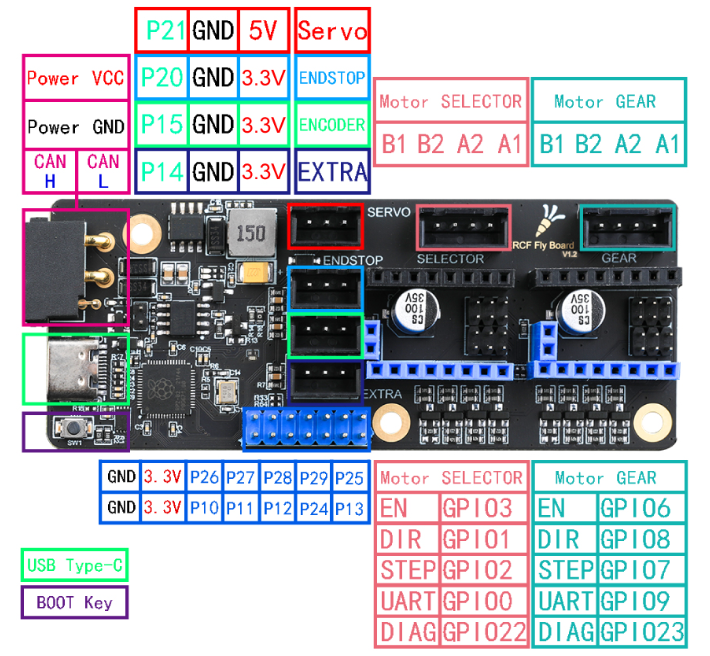
Table of pin functions
| Device | Function | Pin number | Alias |
|---|---|---|---|
| CAN BUS | CAN-RX | gpio4 | |
| CAN BUS | CAN-TX | gpio5 | |
| Selector | EN | gpio3 | S_EN |
| Selector | STEP | gpio2 | S_STEP |
| Selector | DIR | gpio1 | S_DIR |
| Selector | UART | gpio0 | S_CS |
| Selector | DIAG | gpio22 | S_DIAG |
| Gear | EN | gpio6 | G_EN |
| Gear | STEP | gpio7 | G_STEP |
| Gear | DIR | gpio8 | G_DIR |
| Gear | UART | gpio9 | G_CS |
| Gear | DIAG | gpio23 | G_DIAG |
| Endstop | Endstop | gpio20 | STOP |
| Encoder | Encoder | gpio15 | ENCODER |
| Extra | Extra IO | gpio14 | EXTRA |
| Servo | Servo | gpio21 | SERVO |
| IO Expanison | Expansion | gpio26 | IO_1 |
| IO Expanison | Expansion | gpio27 | IO_2 |
| IO Expanison | Expansion | gpio28 | IO_3 |
| IO Expanison | Expansion | gpio29 | IO_4 |
| IO Expanison | Expansion | gpio25 | IO_5 |
| IO Expanison | Expansion | gpio10 | IO_6 |
| IO Expanison | Expansion | gpio11 | IO_7 |
| IO Expanison | Expansion | gpio12 | IO_8 |
| IO Expanison | Expansion | gpio24 | IO_9 |
| IO Expanison | Expansion | gpio13 | IO_10 |
Sample Configuration file: Fly-ERCF-Easy-BRD-V1.1.cfg
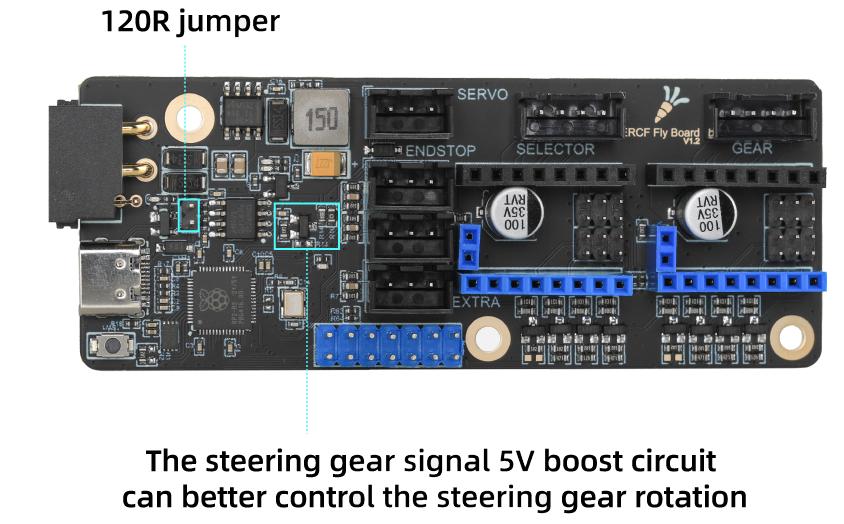
CANbus Termination Resistor
CANbus bus protocol there must be only two 120 ohm resistors on a bus.
No matter how many USB devices you connect, as long as it is on the same bus only two 120-ohm resistors are to be configured. These resistors should be at either ends of the bus.
After connecting CAN H and CAN L signal lines, use a multimeter to measure between CAN H and CAN L. The resistance between the two should be 60 ohms.
XT30 2+2 Wiring
| *Color | Function |
|---|---|
| RED | 12/24V |
| BLACK | GND |
| YELLOW | CAN H |
| WHITE | CAN L |