Overview
This page covers any general information for the Fly-Super 5 Pro boards.
It is currently available through AliExpress.
This is the information for the Fly Super 5 Pro with STM32H723 CPU.
- 32-bit ARM Cortex-M7 Kernel 550MHz, STM32H723ZGT6 Chip
- 5A 5v power supply
- Supported Firmware: Marlin 2.0, Reprap, and Klipper
- Drivers supported: A4988, LV8729, DRV8225, TMC2208, 2209,5160, & 5160HV.
- Drive mode support: TMC: UART, & SPI
- Support for 5 independent motor drives, 2 extruders, and 4 PWM fans
- All drivers sockets support up to 48 volts.
- Supported Displays: serial touch screen, 12864 LCD, 2004 LCD , FLY 4.3, & 7.0 V1
- Supports automatic bed leveling sensor: BLTouch
- 3 ADC interfaces
- 6 I/O ports
- 1 high voltage IN port
- Optional limit switch power supply: 5V, 12V, & 24V
- Optional -On-board WiFi module supported with Reprap firmware.
- PWM Fan MOS boards can be directly replaced in case of damage.\
- On-Board 8Mhigh speed CAN-FD interface
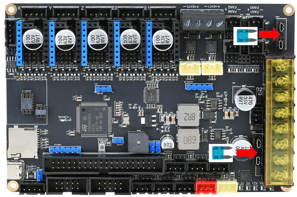
Board Fuses
The board is supplied without the fuses installed. The fuse should be installed before powering on.
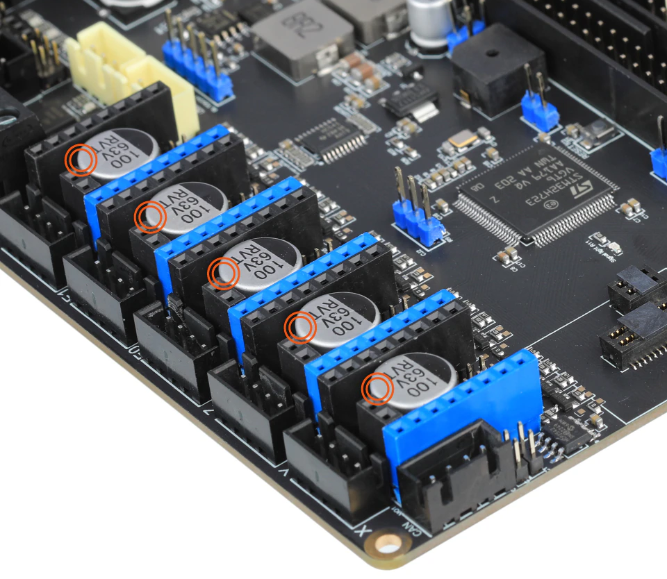
Thermistor inputs
The Fly-Super5Pro H723 supports PT1000 on the thermistor inputs by using a 2k2 resistor rather than a 4k7.
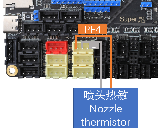
Thermistor Connection
Thermistors should use the ADC inputs. The thermistors should be connected between ground and the signal pin.
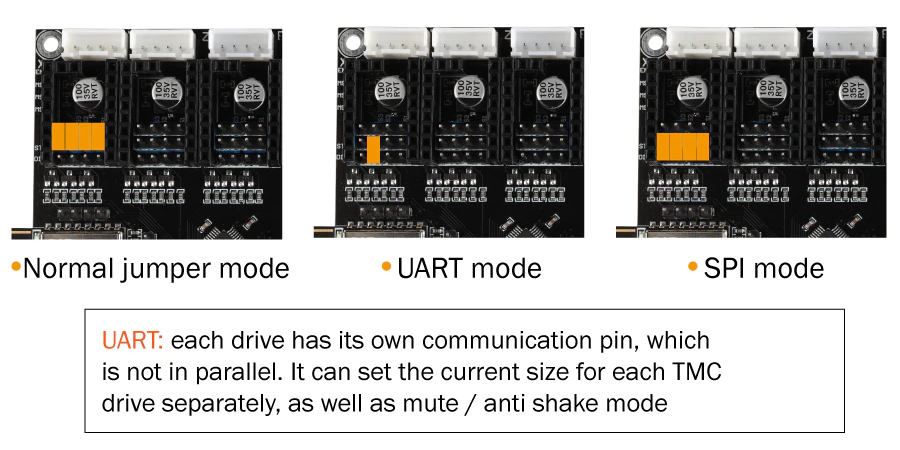
Driver Jumpers
The jumpers should be installed as below. “Common Interpolation” should be used for standalone drivers. “SPI mode Interpolation” is supported for TMC5160 drivers. “UART mode Interpolation” should be used when using smart drivers (i.e. TMC2208, TMC2209, TMC2225 and TMC2226)
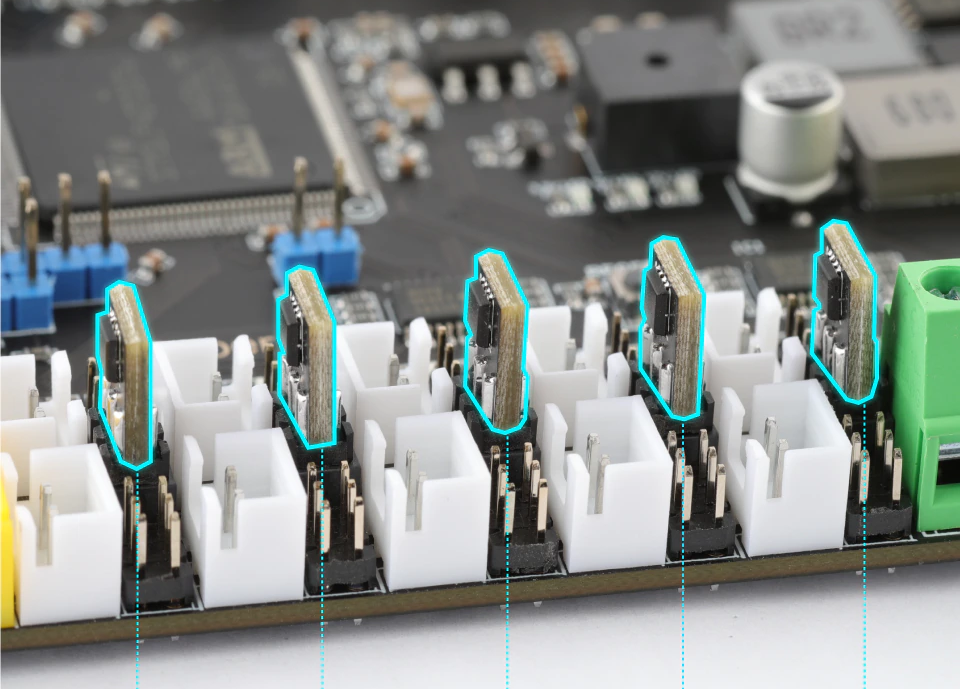
Driver Diag Pin
The driver diag pin is used for sensorless homing and stall detection.
The Fly-Super 5 Pro does not have a way of disabling the diag pin as it is designed to be used with Fly-2209 drivers which have a switch on the underside of them for disabling the diag pin. Set the dip switch to ‘ON’ to enable the diag pin.
If you plan on using endstops rather than sensorless homing and do not have the Fly-2209 drivers, you need to bend or remove the diag pin.
Fan Mosfets
The Fly-Super 5 Pro features 2 replacable fan mosfet modules (VS3622e) that control 4 fan outputs.
If the MOSFET is damaged by an accidental short circuit it can easily be replaced. New Fly-MOS modules can be purchased from the Mellow store
The Fan-MOS design allows it to be inserted in either orientation.
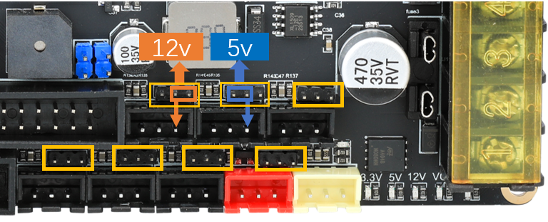
Fan Voltage
The fan voltage can be set using jumpers to either 5v, 12v and Vin.
Set them as shown below.
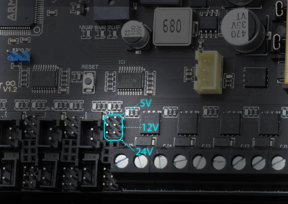
Endstop Output Voltage
The Endstop output voltage can be set to either 5v or 12v. The default is 0v until a jumper is added.
Maximum Input voltage
Board/Bed Power
The main board and heated bed power inputs can handle voltage up to 30v.
Driver Power
Fly-Super 5 Pro driver power inputs can handle voltage up to 62v.